


Please Leave Us A Message
Privacy statement: Your privacy is very important to Us. Our company promises not to disclose your personal information to any external company with out your explicit permission.
 January 13, 2021
This article describes the transformation and display circuit of the Laser Power Meter. The main function of this circuit is to directly indicate the size of the Laser power. The circuit converts the analog voltage output by the laser power meter into a digital pulse output, and displays the frequency of the output pulse in real time, and has the characteristics of high accuracy, good linearity, and stable operation.
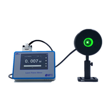
In atomic nucleus physics experiment, it is necessary to measure the atomic photoelectrical cross section with a laser generating a laser with a certain energy. The experiment requires knowledge of the laser power generated by the laser generating device. In order to understand the size of the laser power simply and conveniently, a laser power meter was used in the experiment. Its output is an analog voltage. The amplitude of the analog voltage varies with the laser power. In order to facilitate the experimenter to observe and record data in real time, the circuit is designed and developed. The main function of the circuit is to convert the analog voltage output by the power meter to a corresponding digital pulse output. The pulse can be directly recorded. The pulse frequency is proportional to the output analog voltage of the power meter, which is proportional to the power of the laser. At the same time, the circuit also displays the frequency of the output pulse signal in real time.
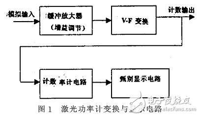
1, the basic circuit compositionThe circuit is mainly composed of four parts: a buffer amplifier circuit, a VF converter circuit, a count rate meter circuit, and a discrimination display circuit. The output pulse signal of the VF conversion circuit is output all the way to the count rate meter circuit, and the other way is directly used as the count output. The count output can be directly sent to the scaler or the data acquisition system. Laser power meter conversion and display circuit block diagram shown in Figure 1. The circuit is installed in a standard double-wide NIM plug-in. Two relatively independent working channels are installed in a double-wide NIM plug-in. The signals output from the two laser power meters can be simultaneously acquired and displayed.
2.1, buffer amplifier
In order to meet the requirements of different amplitude signal measurement and data acquisition, a buffer amplifier was designed with an input signal of 0-2V. Mainly by the buffer level and amplification of two parts. The buffer level is a follower composed of LF356. The amplifier stage consists of coarse gain and fine tuning. Both stages are constructed using operational amplifier LF356. Gain coarse adjustment is divided into & TImes; 1, & TImes; 10, & TImes; 100 third gear, & TImes; 1 gear is selected by the selection switch, × 10, × 100 files can be selected and set by the gain adjustment jumper Jumper. Gain Fine Level Magnification can be achieved by changing the resistance of the potentiometer. The gain adjustment range is 0 to 10 times. The basic circuit structure of the amplifier stage is shown in Figure 2. The first-stage amplification can be adjusted by the selection of jumpers J3 and J4; the second-stage amplification is adjusted by the potentiometer R115.
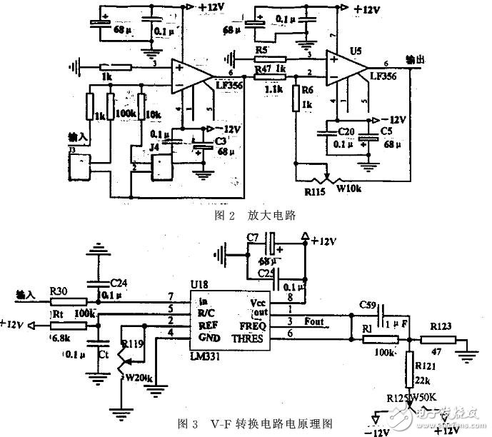
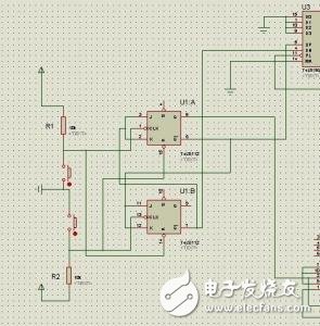
2.2, VF conversion circuit
It is a key part of this circuit. It converts the input analog voltage signal into a regular pulse signal output. The frequency of the pulse signal is proportional to the input analog voltage. The LM331 is used here to form a VF converter. LM331 is a kind of general-purpose integrated circuit, very suitable for voltage frequency conversion, the frequency of the output pulse signal is exactly proportional to the input voltage, it has all the advantages of voltage and frequency conversion technology. It consists of a 1.9V reference voltage, a current switch, a comparator, a bistable multivibrator, and the like. The basic circuit diagram of the VF conversion circuit is shown in Figure 3. The VF conversion circuit converts the voltage input to a frequency output, and the output frequency is given by
2.3, count rate meter circuit
In order to be simple and intuitive, and to indicate the trend of the frequency of the output signal of the VF conversion circuit in real time, ie to indicate the trend of the laser power in real time, a count rate meter circuit scheme is adopted. It counts the pulses input in unit time and gives the output voltage proportional to the input pulse frequency. The counting rate meter circuit charges the capacitor C based on the current pulse, and the capacitor C discharges in parallel with R, and measures the average pulse count rate by measuring the current flowing through the resistor R when the capacitor is charged and discharged, or the voltage across the resistor. Measurement.
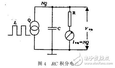
Figure 4 shows a simple RC circuit, assuming that the signal source produces input current pulses Ii(t) with an average count rate of N. Ii(t) has a constant amplitude and width, and each current pulse contains a charge of Q. It can be seen that for each pulse, the capacitor is charged with Q at both ends. Since the average count rate is N, the charge on the capacitor per unit time is NQ, and the charge on capacitor C is also discharged through resistor R. When the capacitor is charged and discharged in balance, the discharge current I flowing through R average = NQ ∝ N, and the average value V of voltage drops generated on R average = NQR, so the pulse count rate N can be read from the output voltage. Taking into account the measurement accuracy and circuit implementation, a simple RC circuit can not fully meet the requirements, and thus designed a diode pump circuit (Figure 5a) and improved diode pump circuit (Figure 5b) and other principles of the circuit can be used to constitute the count rate meter Circuit.
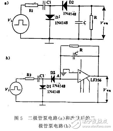
The design of the count rate meter circuit is an improved diode pump circuit. The basic principle of the diode pump circuit is shown in Figure 5a. It consists of diodes D1 and D2, a fixed capacitance C1, an integral capacitor C, and a resistor R. Ri is the internal resistance of the signal source in the figure. . When the input pulse arrives, C1 is charged through internal resistances Ri and D1. After the input pulse, D1 is cut off. The charge on C1 is discharged through D2 and C. Usually, C C1 and C1 discharge to a steady state, and they are charged on C1. The charge is redistributed to capacitor C. The voltage at both ends of C increases after each charge. If the voltage across C and R rises to V average, then C1 discharges to a steady state and V averages, and then the charge Q transferred from C1 to C is (Vi-V average) C1, because of the V-average, the increment Q of the charge on C every time decreases as the V-average increases, not a constant amount. If the input pulse count rate is N, then the charge that is charged to C per unit time is (Vi-V average) C1N. When charging and discharging are balanced, the charge current and the discharge current must be equal, that is, (Vi-V average) C1N=I average =Vaverage/R, then Vaverage = [NRC1/(1+NRC1)Vi]. Thus, there is a non-linear relationship between Vaverage and N. In order to improve the nonlinearity of the diode pump circuit, the count rate meter circuit is designed. The improved diode pump circuit is used. The basic principle is shown in Figure 5b. It uses an operational amplifier to form an integrator. The potential at point A is always close to zero (virtual ground), so that the average change in output V is almost independent of Vi's charge to C1 and C. The charge on C is incremented by each pulse action. Q is constant. At this time, the charge charged to C per unit time is QN. When charging and discharging are balanced, QN=I average=V average/R, so that the output voltage of the circuit has a linear relationship with the input pulse count rate.
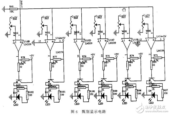
2.4, identify the display circuit
This unit circuit displays the unit time in 6-step counts and is indicated by an LED. Identify the display circuit (Figure 6). Mainly consists of the operational amplifier LM339, when the input potential (the input voltage is given by the output of the count rate meter circuit) is greater than the pre-set potential of the corresponding screening unit, the screening unit output goes high, driving the corresponding indicator LED is bright .
The design and debugging of the completed laser power meter's conversion and display circuit have high measurement accuracy, reliable working performance and good stability, and various technical indicators have reached the design requirements.
The above is the About the conversion and display circuit of laser power meter we have listed for you. You can submit the following form to obtain more industry information we provide for you.
You can visit our website or contact us, and we will provide the latest consultation and solutions
Send Inquiry
Most Popular
lastest New
Related Products
Send Inquiry
Privacy statement: Your privacy is very important to Us. Our company promises not to disclose your personal information to any external company with out your explicit permission.
Fill in more information so that we can get in touch with you faster
Privacy statement: Your privacy is very important to Us. Our company promises not to disclose your personal information to any external company with out your explicit permission.